- Create 3D data using your preferred 3DCG software
- Import the 3D data into Pepakura Designer
- Unfold the model with a single click
- Edit the unfolded pattern as needed
- Print the pattern
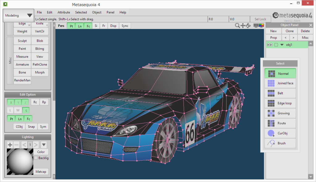
1. Create 3D data
Pepakura Designer focuses on crafting paper models and does not include tools for designing 3D data. Before diving into Pepakura Designer, make sure you have your 3D model data ready to go.
Pepakura Designer supports a range of popular 3DCG file formats, including OBJ, 3DS, and STL. Feel free to use your favorite 3DCG software!
If you’re uncertain about which 3DCG software to use, we highly recommend Metasequoia. It’s not only free but also boasts high compatibility with Pepakura Designer, making it a seamless and cost-effective choice for designing your 3D models.
2. Import the 3D data into Pepakura Designer
To import 3D data into Pepakura Designer, simply go to [File] and select [Open].
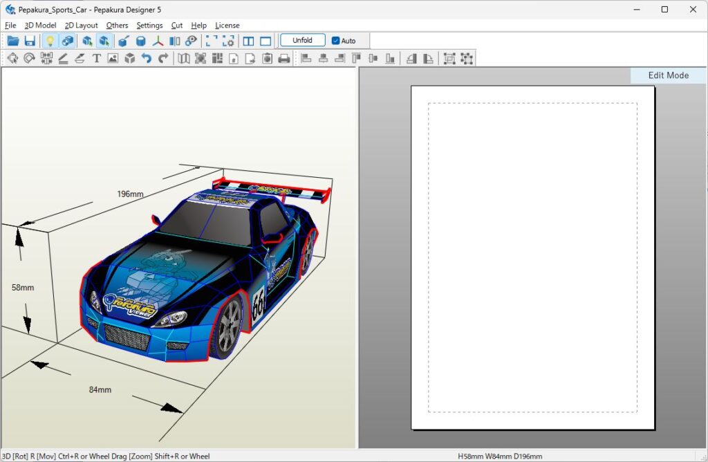
Once imported, your 3D model will be displayed in the left 3D Window. You can manipulate the view using your mouse:
- Rotate by dragging the right mouse button.
- Move the model by dragging the mouse wheel or using [Ctrl] + right drag.
- Zoom in or out with the mouse wheel or [Shift] + right drag.
Want to cut along specific edges during the unfolding process? Head into editing mode by selecting [3D Model] > [Edit Mode] > [Specify Cutting Edges], and click on the edges you want to define as cut lines. They will turn orange to indicate they are selected.
By default, nearly flat edges are hidden to reduce clutter. If you need to see them, simply uncheck the option under [Settings] > [Others] > [Line Style] > [Hide nearly flat folding lines].
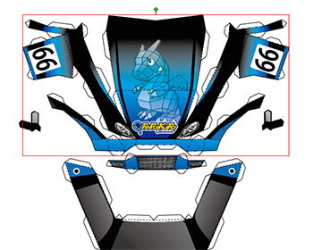
3. Unfold the model with a single click
Press the [Unfold] button to automatically generate the unfolded patterns.
If you need to specify the size of the patterns, uncheck the [Auto] checkbox next to the Unfold button before initiating the unfolding process. This will allow you to manually set the dimensions.
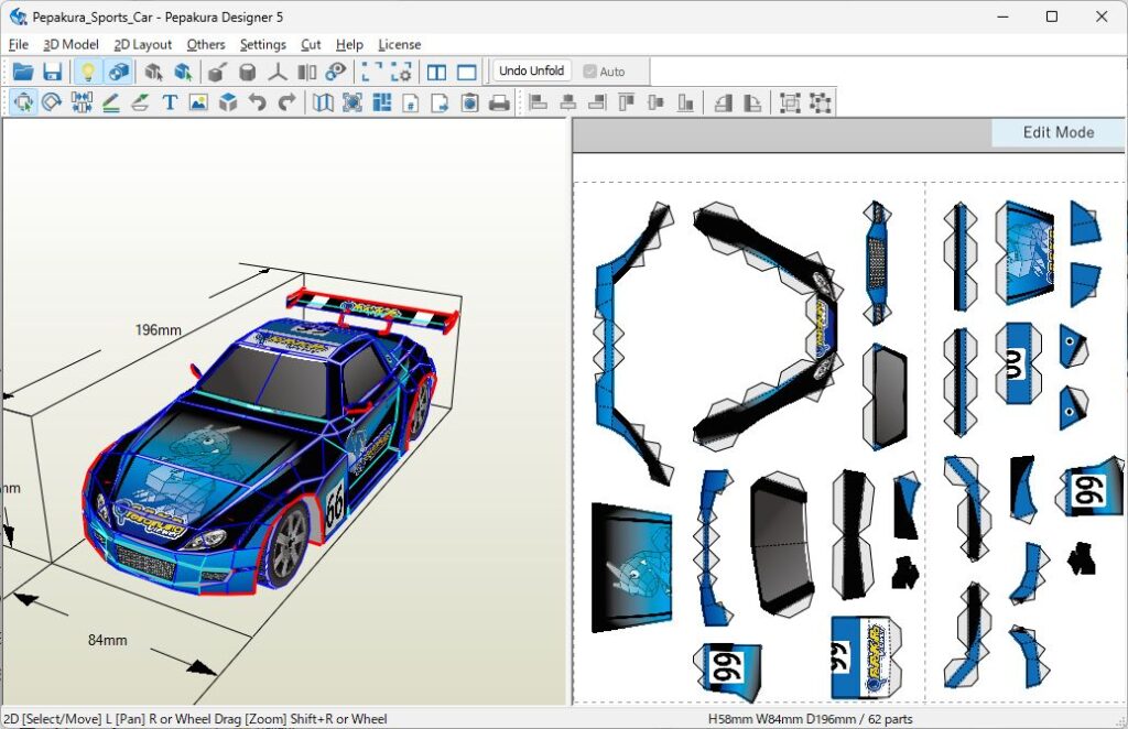
4. Edit the Unfolded Pattern
You have the ability to modify the layout of the unfolded pattern, including connecting or disconnecting parts, and altering the width of flaps (tabs).
Switch between editing modes using [2D Layout] > [Edit Mode] (or through the right-click menu).
Mouse operations allow you to manipulate the view in the 2D window:
- Translation: Right Drag or Wheel Drag
- Zoom: Wheel or [Shift] + Right Drag
4.1 Translations and Rotations of Parts (In [Select and Move] Mode)
Use a left mouse click-and-drag to move the selected parts. To select multiple parts simultaneously, you can either hold down the [Shift] key and click on the parts, or create a rectangle around the parts by performing a left mouse click-and-drag. Dragging the green point at the top of a part allows you to rotate the part.
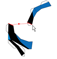
4.2 Connecting and Disconnecting Parts (In [Join/Disjoin Faces] Mode)
To connect two parts together along a specific edge, click on that edge. An arrow will indicate the direction in which one part will move to align with the other. The arrow’s direction changes as you move the mouse cursor across the screen. Click anywhere to complete the connection of the parts.
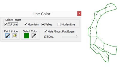
4.3 Changing the Color or Visibility of Lines (In [Edge Color] Mode)
To alter the colors of the edges, first select the desired color, and then click on the edges individually. You can also use a left mouse click-and-drag to select multiple edges and apply the color to them simultaneously.
When the Eraser icon is selected, any edges you click on will be hidden.
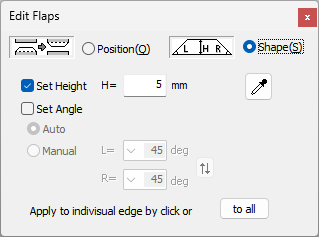
4.4 Editing Flaps (Tabs) (In [Flaps] Mode)
There are two sub-modes: [Switch] and [Change Shape].
In [Switch] mode, clicking on an edge toggles the location of the flaps.
In [Change Shape] mode, clicking on a flap allows you to modify its shape according to the options available in the dialog.
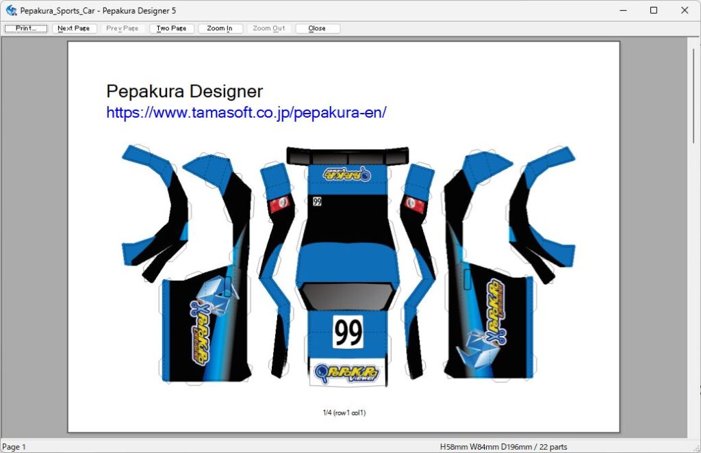
5. Printing the Unfolded Pattern
Print the unfolded pattern by navigating to [File] > [Print].
You can modify the sheet size and line thickness by going to [File] > [Print and Paper Settings].
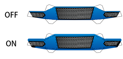
For cleaner assembly, consider adding offsets to the boundaries by checking [2D Layout] > [Add Outline Padding]. This feature can be especially helpful for creating more polished models.
Now that the printing is done, let’s cut out the parts and assemble them!